[ Cumpiano GUITARS ] [ CLASSES ] [ NEWSLETTERS ] [ ARTICLES ] [ TEXTBOOK ] [ Links ] [ Scrapbook ]
GUITARMAKING: Tradition and Technology
A Complete Reference for the Design & Construction of
the Steel-String Folk Guitar & the Classical Guitar
by William R. Cumpiano and Jonathan D. Natelson 392 pages

Hardcover edition soon to be republished by Rosewood Press |
"...perhaps the finest book on
making guitars ever produced."
Guitar Player magazine
"...an unparalleled treasure"
Fine Woodworking magazine
"...the bible of the craft"
C.F. Martin IV, CEO, C.F. Martin Guitar Company |

Softcover edition published by Chronicle Books
|
Updates, changes, feedback,
commentary and clarifications
Retrospective thoughts
The history behind the writing of GUITARMAKING.
Headblock dimension typo error in early editions
Upper transversal graft dimension error in early
editions
Options for the pinned mortise neck joint
Swapped captions in the classic bracing sizes diagrams
Tips on obtaining rubber rope
Workboard shim clarification
Workboard clamping shoe caveats
Interior fingerboard glueing caul (classic):
additional comments
"It says to leave only 1/8" for the nut!"
"Difference between the classic headblock and
tailblock heights only 1/8?"
"Where are all the French Polishing
details?"
Improved truss rod design
Retrospective Thoughts
Jon and I wrote this book in 1985, and to my
great joy and satisfaction, it has become a perennial bestseller, and consequently the
standard textbook in the guitarmaking field. It was truly a labor of love, its creation
being an enormous challenge, burden and sacrifice (writing
the book was like "enduring a protracted illness") but the payoffs have been
ample: over the years I have made countless friends and thankful acquaintances as a direct
consequence of that effort. Proudly, I have watched the field blossom with a great number
of new, fine builders which have "graduated" from the book and from their
additional efforts and sacrifices. Together with a burgeoning market for fine handcrafted
guitars, these many new builders have entered the field and lifted American guitarmaking
into a true Golden Age. I'd like to think that my book has contributed to this resurgence.
Return
Headblock dimension
error in early editions
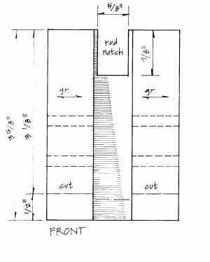
The earliest (hardcover) Rosewood Press editions of the book had a
glaring dimension error in diagram 9-6 on page 191 captioned "The mortised headblock
three-view (steel string)" It showed the over all height of the headblock as 3
5/8" PLUS the 1/2" height of the angled cutoff segment on its bottom.
People following this would have ended with a headblock on the guitar which was
considerable taller than it should be (some folks informed me that they just trimmed it
off). The error was corrected in subsequent editions which properly showed that the
overall height of the blank was 3 5/8 BEFORE the 1/2" angled cutoff segment was sawn
away--leaving a headblock with its mortised end 3 1/8" in height. For those with the
older editions, here's a scan of the corrected version found in the corrected editions and
the paperback:

Return
Upper Transversal Graft
dimension error in early editions
In early editions of GUITARMAKING, diagram 7-7b on page 15
showing the "schedule of final finished brace-blank cross sections" has
a dimensional error shown for the steel string UTVGFT (upper transversal graft). It shows
the width of the graft as being 1". In later editions, this was corrected to show
7/8", after it was realized that the space alloted for it between the headblock and
the upper transversal face brace was 1", and you can't fit a 1" object into a
1" hole!
Return
HARDWARE BASED
NECK JOINT
A new hardware-based neck joint
replaces the recommended pinned mortise-and-tenon joint. Easier, better. If anyone wants
to argue the merits or demerits of hardware, I'm game. But please don't do so on emotional
grounds. I'd rather you'd confront me with hard engineering or acoustical evidence (or
even precedents) to bolster your case
Return
SWAPPED CAPTIONS
A reader discovered swapped captions on the CLASSIC section
of diagram 7-7b on page 151. The handwritten legends for "ros.gft (2) 4"L"
and "utvgrft (1) 5 1/2" are mistakenly swapped. No profound consequence. These
grafts are minor components simply used to "strap" the soundboard fibers
together at weak areas, or areas of shear stress, and their precise length or width are
not a critical factor in the sound or stability of the guitar.
Return
TIPS ON RUBBER
ROPE
Readers are complaining that automobile inner tubes for
making the rubber rope (for roping the back while glueing it onto the
guitar shell) are getting harder and harder to get, and while the book text discourages
people from using a truck inner tube (because its "too heavy") it seems
expedient to recommend these now--because these indeed are far more common to find since
they are not obsolete. Check the Yellow Pages for truck repair shops. You may have to
slice the rope into a slightly narrower band than what's indicated in the book, but you'll
get a far, far longer strip than if you had used an automobile tube.
RETURN
WORKBOARD SHIM
The diagram on page 36, figure 3-5b shows a dotted rectangle
in the middle of the shim. The text describes this as where a small piece of cork should
be glued.The shim supports the transversal face braces right under the workboard shoe. The
text does not suggest that in addition, since the lower cross strut is arched, the
clearance to the workboard is reduced and thus you should sand that piece of cork until it
is thinner by the indicated arch deflection--than the outer cork lining.
RETURN
CLAMPING SHOE
I should add the following update comments: You must be
careful when tightening down the clamping shoe over these shims. The thumbscrew or bolt
must be snugged down firmly but be aware that if you bully the tightening of the clamping
shoe, it is entirely possible to collapse the tiny cork rectangles and break something on
the top. My concern over this possibility has driven me in recent years to dispense with
the corkboard shim altogether, and hollow out the workboard with a scraper blade directly
under where the arched lower transversal (CL) or the arch upper transversal and x-brace
(SS) is expected. It is a choresome step, but probably better technique in the end. Use
the same arch template that you used to arch the brace, as you check your progress while
scraping the hollow in the workboard. Extend the scraped area, feathering it up towards
where the soundhole would be, and down gently towards where the bridge would be. It should
be correct in depth right at the main brace locations, but if it is not strictly accurate
to the way the top would flex below or above the main brace(s), it is not
critical--because the top plate is resilient and will temporarily distort without harm if
the precise curvature of the workboard doesn't precisely match the curvature of the top.
But it should match right under the main brace(s).
RETURN
INTERNAL
FINGERBOARD GLUEING CAUL
Confusion has arisen from:diagram 10-16 on page 220
titled "The upper face brace/cross strut caul." it is indeed the upper face
brace caul for the steel-string, not the classical, and no distinction is made in the
text. A reader building a classic guitar must extrapolate from the text, and use the
actual measurements from the instrument to devise the caul for their classical..I will be
uploading a classical IFG caul diagram soon at this location.
RETURN
It says to leave only 1/8"
for the nut!!
I'm trying a classical. I'm in the process of laying out the head block.
It says to measure an 1/8 of an inch from the line where the plane of the head
meets the plane of the neck and draw a line. This to indictate where the fingerboard
is to begin. But the nut's going to be a 1/4 inch thick. Right?
Shouldn't I leave a 1/4 inch space?
Yeah, it sounds funny, I know. But it makes sense after you read ahead, on Page 63
"Applying Headstock Veneer" and then page 310, Step5-- Classical only: Cutting
Back the Nut Slot." Jon's technique was to cut back the veneer AFTER the fingerboard
is glued down, in case the board ends up wobbled away a bit after the glue dries. It makes
sense, since the maximum thickness nut blanks available commercially come 1/4" thick,
and if it wobbles to 1/4+1/32, then you're going to have a bad fitting nut. His procedure
avoids this possibility.
RETURN
The height difference between the
classic headblock and tailblock is only 1/16" !!
I'm to the point in your book where I'm geting ready to arch the back on the
classical guitar I'm making. I realize that the amount of the arch is much less in the
classical, than on the steel string, but I can't figure out how the arch is supposed to
look if the tail block is 3 3/4 inches and the head block is pretty close to that, at 3
11//16. If it's just 1/16 this seems small enough so that it could be disregarded. I'm
thinking about adding an additional 1/4 to the tail block to provide for a more
significant arch. What do you think?
No, don't add any extra height to the tailblock Remember that the 3 3/4" tailblock
is mounted on the top, so the starting difference is not 1/16" but more like
1/8" to 3/16". The difference will be exacerbated when you trim the sides down
to the proper taper between the two blocks, and then applying the large sanding board.
That will apply a slope to the top of the
headblock, and remove yet another 1/8" or so from the front of the headblock. The
arch on the classic AND the slope of the back are indeed subtle.
RETURN
Alas, no French Polishing
details...<sob>!!
I have gone through your book very throughly as preparation for my building of a
Martin Guitar with their kit. I found the book very well written and extremely helpful.
What I hope to know more about is French Polishing since I don't have the use of spray
equipment available to me. Your book has just that one picture on it and it doesn't really
describe very much. Can you give me some tips and pointers?
My book never intended to cover French Polishing at length. Because first, I am not a
master at it, and second, the directions required are quite lengthy--not that its a long
process, but that it takes a lot of space to explain it properly--and the book had reached
400 pages as is. But you have at least two options:
RETURN
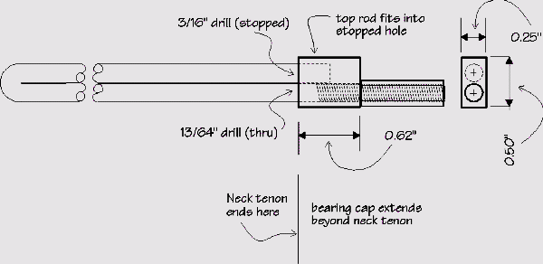
Improved truss rod design

Over the years, I've been using an improved truss rod which has a more massive bearing
cap. The cap on the rod design pictured in diagram 4-16 page 55 simply did not grab
the top rod adequately, and tended to distort and tip under load. This new design will not
distort in the cap area. Wrap the rod with gummed foil as in diagram 4-16


